Chapter 4: Architecture Design
Architecture design for a network identity authentication system requires careful consideration of redundancy, scalability, survivability, and security zone separation. This chapter presents reference architectures for single-site, multi-site, and cloud-hybrid deployments, along with detailed device connection diagrams that illustrate the physical and logical relationships between authentication infrastructure components. Each architecture is accompanied by design rationale, sizing guidance, and key configuration parameters.
4.1 Reference Architecture: Single-Site Enterprise
The single-site reference architecture is designed for organizations with 200–2,000 endpoints concentrated at a single campus or building complex. The architecture places all authentication infrastructure in a dedicated security services VLAN within the data center, with redundant RADIUS servers in active-active configuration. Access switches and wireless controllers are configured as 802.1X authenticators, forwarding EAP traffic to the RADIUS cluster over a dedicated management VLAN. The PKI/CA server issues certificates to managed endpoints via SCEP/EST, while the NAC policy engine provides device profiling and posture assessment.
| Component | Quantity | Placement | HA Model | Sizing Basis |
|---|---|---|---|---|
| RADIUS Server | 2 (cluster) | Data Center Security VLAN | Active-Active | 1,000 auth/s per node; scale at 70% utilization |
| AD/LDAP Server | 2 (DC pair) | Data Center Identity VLAN | Active-Active (AD replication) | Standard DC sizing; 1 DC per 1,000 users |
| PKI/CA Server | 2 (offline root + online sub-CA) | Offline root in vault; sub-CA in DC | Sub-CA clustered | Certificate volume × 2 for renewal headroom |
| NAC Policy Engine | 1–2 | Data Center Security VLAN | Active-Standby | 1 node per 5,000 concurrent sessions |
| TACACS+ Server | 2 | Data Center Management VLAN | Active-Standby | Device count × 10 sessions per device |
| SIEM | 1 (cluster) | Data Center Security VLAN | Clustered | EPS × 1.3 headroom; 180-day retention |
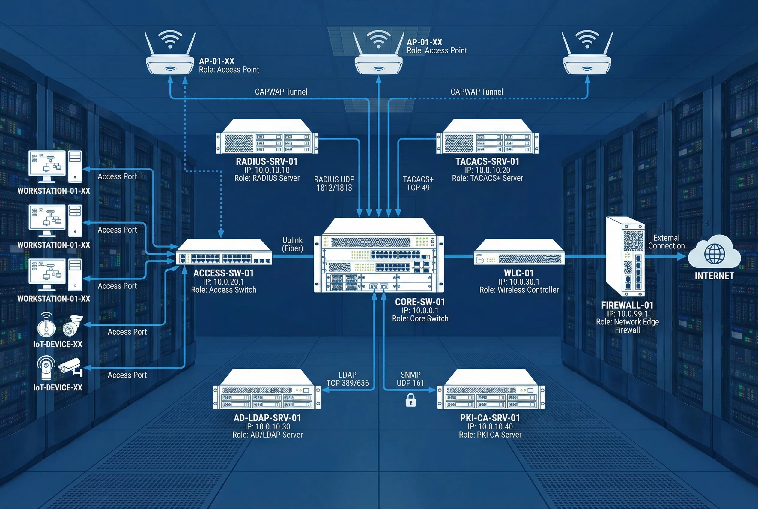
4.2 Device Connection Diagram
The device connection diagram illustrates the physical and logical wiring between all authentication infrastructure components, including protocol labels, port numbers, and IP addressing conventions. This diagram serves as the primary reference for network engineers during deployment and troubleshooting. Each connection is labeled with the protocol, transport, and port number to enable precise firewall rule creation and network segmentation design.
| Source | Destination | Protocol | Port(s) | Purpose |
|---|---|---|---|---|
| Access Switch / WLC | RADIUS Server | UDP | 1812, 1813 | Authentication and accounting |
| Network Devices | TACACS+ Server | TCP | 49 | Admin command authorization |
| RADIUS Server | AD/LDAP Server | TCP | 389 (LDAP), 636 (LDAPS) | User/group lookup, password validation |
| RADIUS Server | PKI/CA Server | HTTP/HTTPS | 80, 443 | OCSP certificate revocation check |
| All Servers | SIEM | TCP/TLS | 6514 | Syslog event forwarding |
| All Devices | NTP Server | UDP | 123 | Time synchronization |
| RADIUS Server | Access Switch / WLC | UDP | 3799 | CoA (Change of Authorization) |
| NAC Engine | Access Switch | SNMP/SSH | 161, 22 | Device profiling and enforcement |
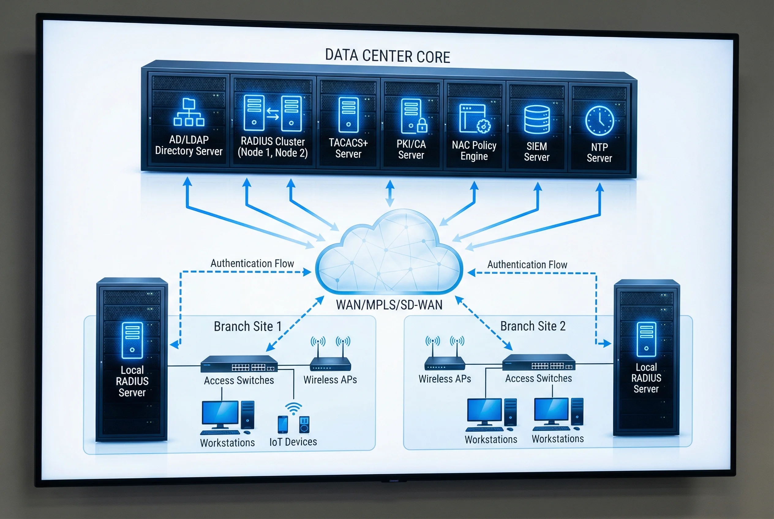
4.3 Multi-Site Architecture
For organizations with 3–30 sites, the multi-site architecture extends the single-site model with WAN survivability and identity replication. Each branch site maintains a local RADIUS server and domain controller that can authenticate users independently during WAN outages. Policy synchronization between the central policy engine and branch RADIUS servers ensures consistent enforcement across all sites. The architecture supports both MPLS and SD-WAN connectivity, with automatic failover between primary and secondary WAN paths.
| Site Type | Local Components | Central Dependencies | Survivability Duration |
|---|---|---|---|
| HQ / Primary Data Center | Full stack (RADIUS, AD, PKI, NAC, SIEM, TACACS+) | None (authoritative source) | N/A (authoritative) |
| Large Branch (> 200 users) | Local RADIUS, Local DC, Local NTP | Central PKI (OCSP), Central SIEM | 48–72 hours (cached policy) |
| Medium Branch (50–200 users) | Local RADIUS (proxy mode), RODC | Central AD, Central PKI, Central SIEM | 24–48 hours (cached credentials) |
| Small Branch (< 50 users) | RADIUS proxy on router/switch | Central RADIUS, Central AD, Central PKI | Static fallback VLAN only |
4.4 Security Zone Design
Proper security zone separation is critical for protecting authentication infrastructure from lateral movement attacks. Authentication servers must be placed in a dedicated security services zone with restrictive firewall rules permitting only the specific protocols and source addresses required for each integration. The management plane must be separated from the data plane, with all administrative access brokered through the PAM jump server. The following table defines the recommended zone structure and inter-zone firewall policy.
| Zone | Components | Inbound Allowed From | Outbound Allowed To |
|---|---|---|---|
| Identity Core Zone | AD/LDAP, PKI/CA, RADIUS, TACACS+ | Network Infrastructure Zone (RADIUS/TACACS+), Management Zone (admin) | SIEM Zone (syslog), NTP Zone |
| Network Infrastructure Zone | Core/Access Switches, WLC, Firewall | User Zone (802.1X), Management Zone (admin) | Identity Core Zone (RADIUS/TACACS+), Internet (filtered) |
| Management Zone | PAM Jump Server, NMS, NTP | Admin workstations (MFA required) | All zones (admin protocols only) |
| SIEM Zone | SIEM, Log Aggregator | All zones (syslog TLS 6514) | SOC workstations, ticketing system |
| User Zone | Workstations, BYOD, IoT | Internet (post-auth), corporate apps (per policy) | Network Infrastructure Zone (802.1X only pre-auth) |
4.5 High Availability and Disaster Recovery
The identity authentication system must achieve an availability target of 99.9% or higher, as authentication downtime directly impacts all network-connected users and devices. The HA architecture employs multiple layers of redundancy: active-active RADIUS clustering with load balancing, AD multi-master replication, PKI sub-CA clustering, and geographic redundancy for critical components. The disaster recovery plan defines RTO and RPO targets for each component, with automated failover for critical services and documented manual procedures for less critical components.
| Component | HA Model | RTO Target | RPO Target | Failover Trigger |
|---|---|---|---|---|
| RADIUS Cluster | Active-Active (N+1) | < 30 s | 0 (stateless) | Node health check failure |
| AD/LDAP | Multi-master replication | < 60 s | < 15 min replication lag | DC unavailability |
| PKI Sub-CA | Active-Standby cluster | < 5 min | 0 (HSM-backed) | Primary CA failure |
| NAC Engine | Active-Standby | < 2 min | < 5 min (session state) | Primary failure |
| TACACS+ Server | Active-Standby | < 60 s | 0 (stateless) | Primary failure |