Chapter 3: Scenarios & Selection
Network identity authentication requirements vary significantly across deployment environments. This chapter presents eight canonical scenarios drawn from enterprise deployments, each with a photorealistic scene, detailed description, key technical indicators, and selection criteria. Understanding these scenarios enables architects to match the correct authentication mechanism, enforcement model, and policy design to each environment's unique risk profile and operational constraints.
Scenario 1: Wired Enterprise LAN — 802.1X EAP-TLS
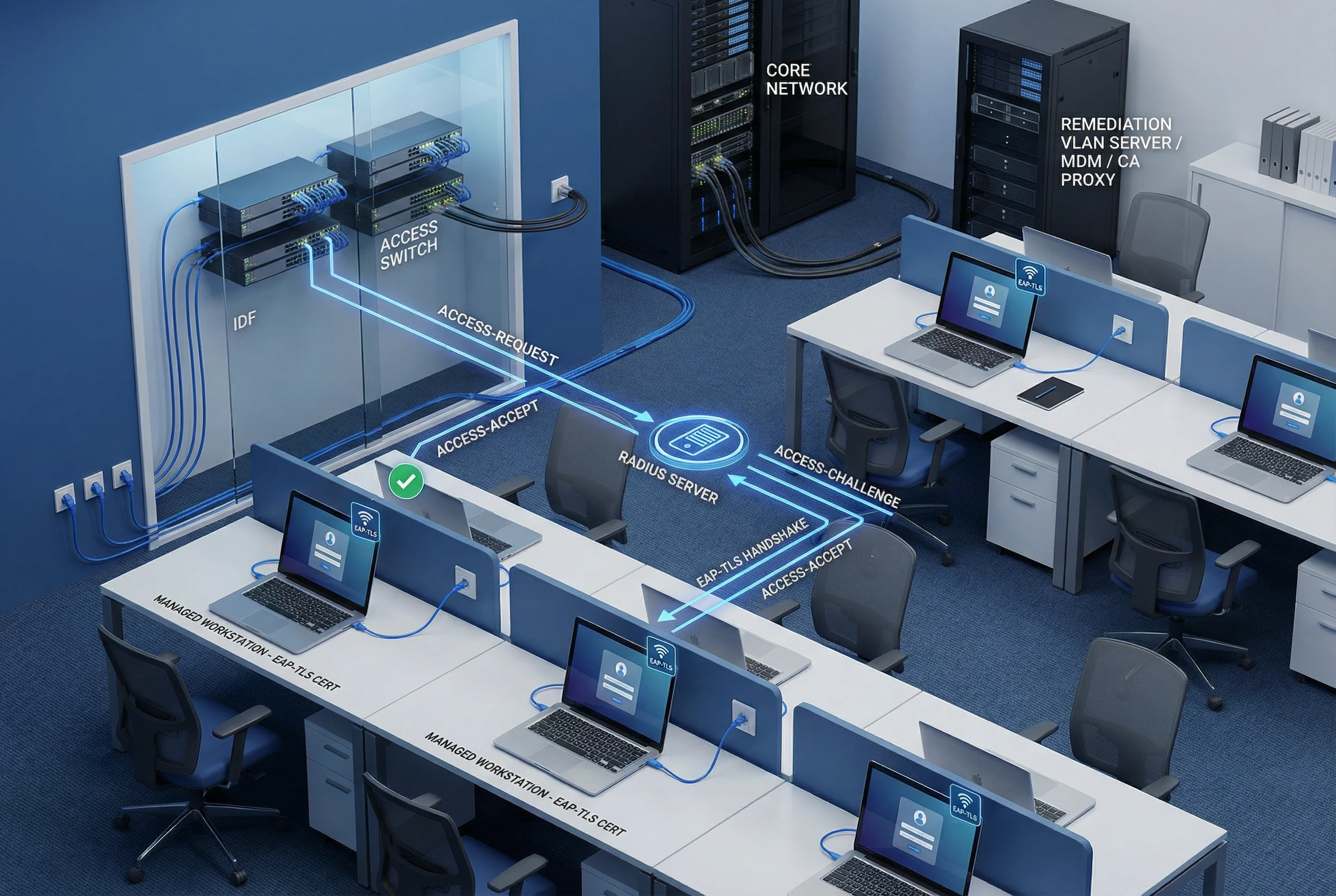
In a wired enterprise LAN, all managed workstations connect via Ethernet to access switches in IDF closets. Each workstation holds a machine certificate issued by the corporate PKI, enabling EAP-TLS mutual authentication. The switch acts as the 802.1X authenticator, forwarding EAP frames to the RADIUS server, which validates the certificate chain and revocation status before returning a VLAN/ACL assignment. Devices without valid certificates are placed in a remediation VLAN where they can access only the MDM and CA proxy for certificate enrollment.
| Technical Indicator | Target Value | Notes |
|---|---|---|
| EAP-TLS coverage | 100% managed endpoints | No PEAP-MSCHAPv2 in production zones |
| Dynamic VLAN assignment | Per-role, per-device | RADIUS attribute: Tunnel-Private-Group-ID |
| MAB fallback (legacy) | Restricted ACL only | Documented exception with expiry date |
| RADIUS cluster HA | N+1 active-active | Failover < 30 s; site survivability for WAN failure |
| Certificate key size | RSA 2048+ or ECDSA P-256 | Enforced via CA template EKU constraints |
Scenario 2: Enterprise Wi-Fi — Multi-SSID Role-Based Access

Enterprise wireless deployments typically require three distinct SSIDs serving different user populations. The corporate SSID uses EAP-TLS with machine certificates for managed devices, providing seamless roaming and dynamic VLAN assignment. A BYOD enrollment SSID provides a limited-access path for personal devices to enroll certificates via SCEP/MDM. A guest SSID redirects unauthenticated users to a captive portal with sponsor approval workflow. The wireless controller acts as the central enforcement point, applying RADIUS-returned VLAN assignments to all associated clients.
| SSID | Auth Method | VLAN Assignment | Access Level |
|---|---|---|---|
| Corporate | EAP-TLS (machine cert) | Dynamic per role | Full corporate access per policy |
| BYOD Enrollment | PEAP-MSCHAPv2 (temp) | Enrollment VLAN only | MDM/CA proxy only; cert issued then migrated |
| Guest | Captive portal + sponsor | Guest VLAN | Internet only; DNS filtered; rate limited |
Scenario 3: IoT Device Tiered Onboarding and Containment
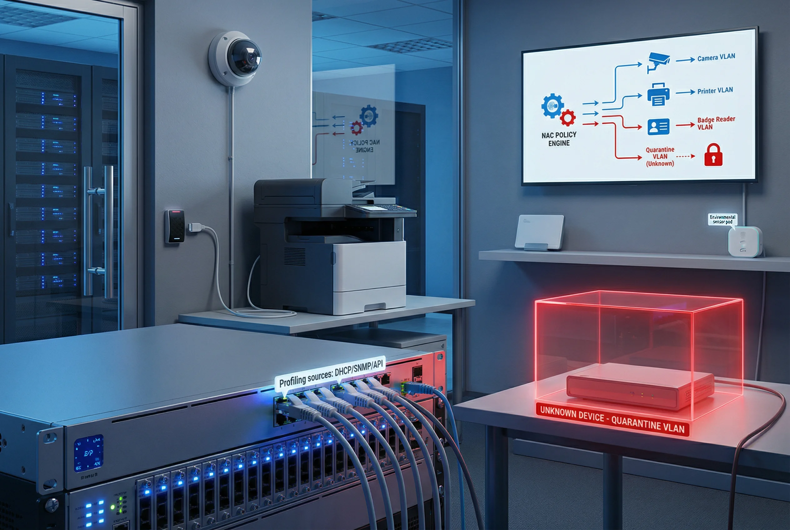
IoT devices — IP cameras, printers, badge readers, environmental sensors — cannot run 802.1X supplicants and require an alternative onboarding model. NAC profiling uses DHCP fingerprinting, SNMP OID matching, HTTP user-agent analysis, and API integrations with asset management systems to classify devices automatically. Each device type is assigned to a dedicated IoT VLAN with a restrictive ACL permitting only the specific ports and destinations required for its function. Unknown devices are automatically placed in a quarantine VLAN pending manual review or automated remediation.
| Device Type | Profiling Source | Assigned VLAN | ACL Restrictions |
|---|---|---|---|
| IP Camera | DHCP + HTTP UA | Camera VLAN | Allow only NVR server; deny all else |
| Network Printer | DHCP + SNMP OID | Printer VLAN | Allow print ports; deny internet |
| Badge Reader | DHCP + MAC OUI | Access Control VLAN | Allow only access control server |
| Environmental Sensor | DHCP + API | Sensor VLAN | Allow only BMS/SCADA server |
| Unknown | No match | Quarantine VLAN | Deny all; alert to SIEM |
Scenario 4: Visitor and Guest Network Management
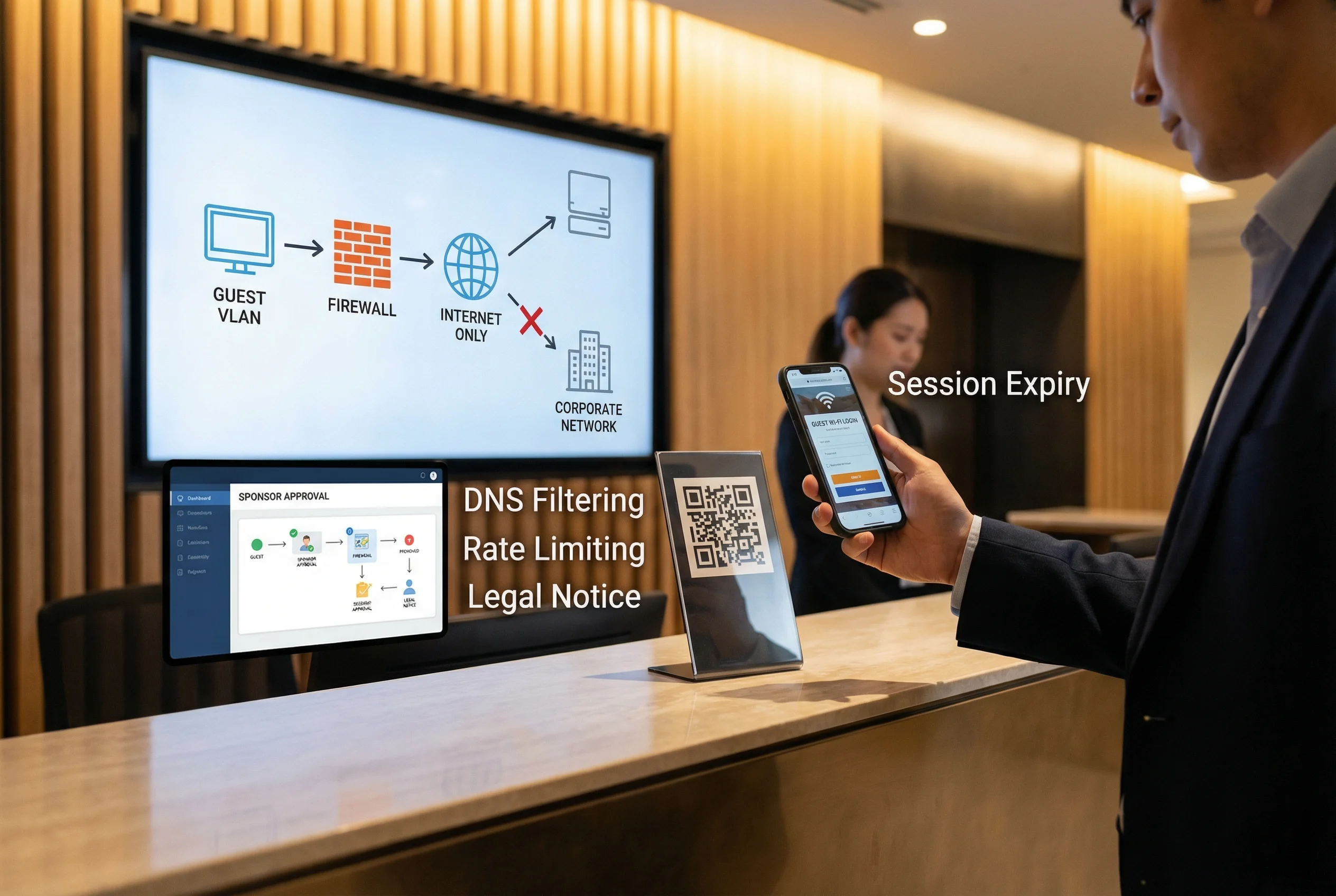
Guest network management must balance hospitality with security. Visitors scan a QR code at reception, which redirects their device to a captive portal requiring either a sponsor approval or a self-service registration with legal notice acceptance. The guest VLAN is strictly isolated from the corporate network at the firewall level, with DNS filtering to block malicious domains, bandwidth rate limiting to prevent abuse, and automatic session expiry to prevent credential sharing. Sponsor approval workflows integrate with email or ITSM systems for accountability.
| Control | Implementation | Purpose |
|---|---|---|
| Captive portal | NAC-hosted; HTTPS redirect | Collect identity and legal consent |
| Sponsor approval | Email link or ITSM ticket | Accountability for guest access |
| VLAN isolation | Firewall deny-all to corporate | Prevent lateral movement |
| DNS filtering | Category-based block list | Block malware/phishing domains |
| Rate limiting | Per-user bandwidth policy | Prevent bandwidth abuse |
| Session expiry | Automatic after TTL | Prevent credential sharing |
Scenario 5: Remote Workforce — MFA + ZTNA Conditional Access
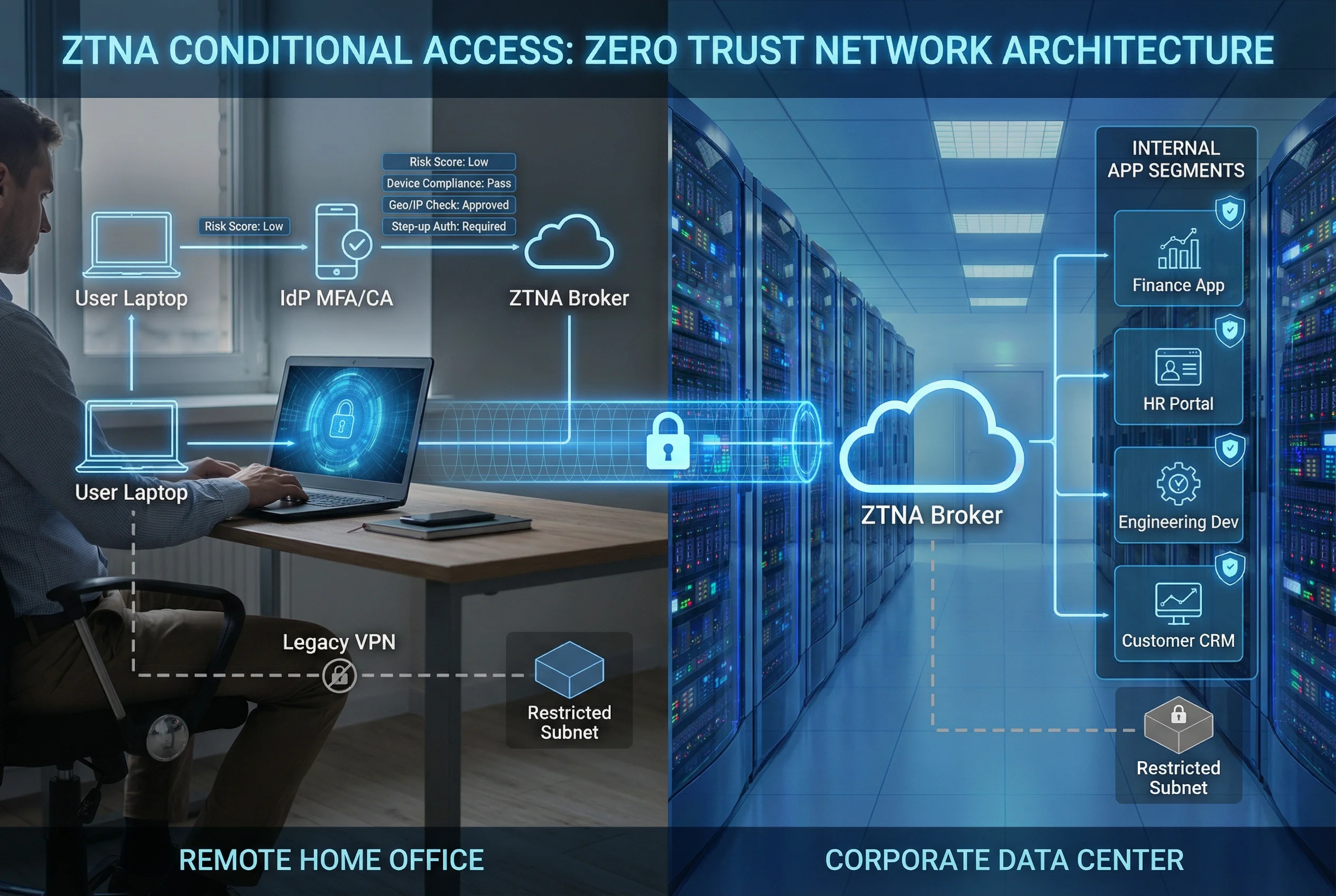
Remote workforce access requires continuous verification of user identity, device health, and contextual risk signals. The ZTNA model replaces traditional VPN with per-application access control. Users authenticate to the IdP with MFA, which evaluates risk signals including device compliance (MDM/EDR status), geographic location, IP reputation, and time-of-day patterns. High-risk sessions trigger step-up authentication or are blocked entirely. Legacy VPN is retained only for specific legacy applications with restricted subnet access. All sessions are logged with correlation IDs for forensic traceability.
| Risk Signal | Source | Policy Action |
|---|---|---|
| Device compliance | MDM/EDR API | Non-compliant → quarantine or step-up |
| Geographic location | IP geolocation | Unexpected country → step-up or block |
| IP reputation | Threat intel feed | Known bad IP → block immediately |
| Time-of-day | Policy engine | Off-hours access → step-up required |
| Velocity anomaly | IdP analytics | Impossible travel → block + alert |
Scenario 6: Privileged Access Management — PAM + TACACS+

Privileged access to network devices and servers requires the highest level of accountability. All administrative sessions are brokered through a PAM jump server, which enforces MFA, credential checkout with time-limited TTL, and full session recording. TACACS+ provides command-level authorization based on the admin's role, denying unauthorized commands and logging every permitted command with user identity and timestamp. Break-glass emergency procedures are documented and audited, requiring post-incident review. Shared admin accounts are prohibited; every admin uses a unique identity.
| Admin Role | Permitted Commands | Denied Commands | Approval Required |
|---|---|---|---|
| Network Operator | show, ping, traceroute | config, reload, erase | No |
| Network Engineer | show, config interface/VLAN | erase, reload, global routing changes | Change ticket |
| Network Admin | All except erase/reload | erase startup-config, reload | Change ticket |
| Break-Glass | All commands | None (emergency) | Post-incident review |
Scenario 7: Multi-Site Identity Federation and Survivability
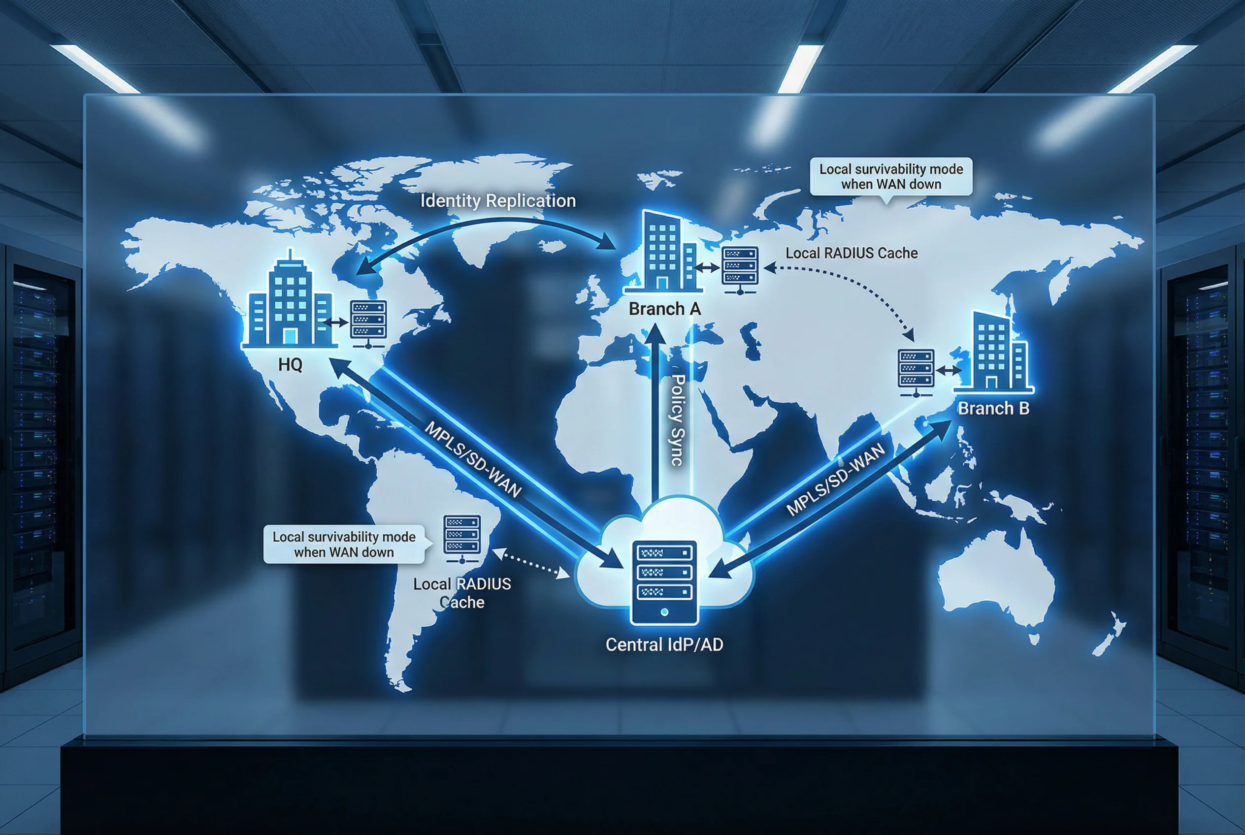
Organizations with multiple sites require a federated identity architecture that provides both centralized policy control and local survivability. The central IdP and AD serve as the authoritative identity source, with identity data replicated to local domain controllers at each site. Each site maintains a local RADIUS/TACACS+ server that caches policy decisions and can authenticate users independently during WAN outages. Policy synchronization ensures that changes made centrally propagate to all sites within a defined SLA. The architecture supports 8–30 sites with consistent policy enforcement regardless of WAN availability.
| Condition | Authentication Path | Policy Source | Limitations |
|---|---|---|---|
| WAN available | Local RADIUS → Central AD/IdP | Central policy engine | None |
| WAN degraded | Local RADIUS → Local DC | Cached policy (last sync) | New policy changes not applied until WAN restored |
| WAN down | Local RADIUS → Local DC cache | Cached policy | No new user provisioning; no cert revocation updates |
| Complete site isolation | Local fallback VLAN | Static fallback rules | Restricted access only; alert generated |
Scenario 8: SIEM-Integrated Identity Audit and Alerting
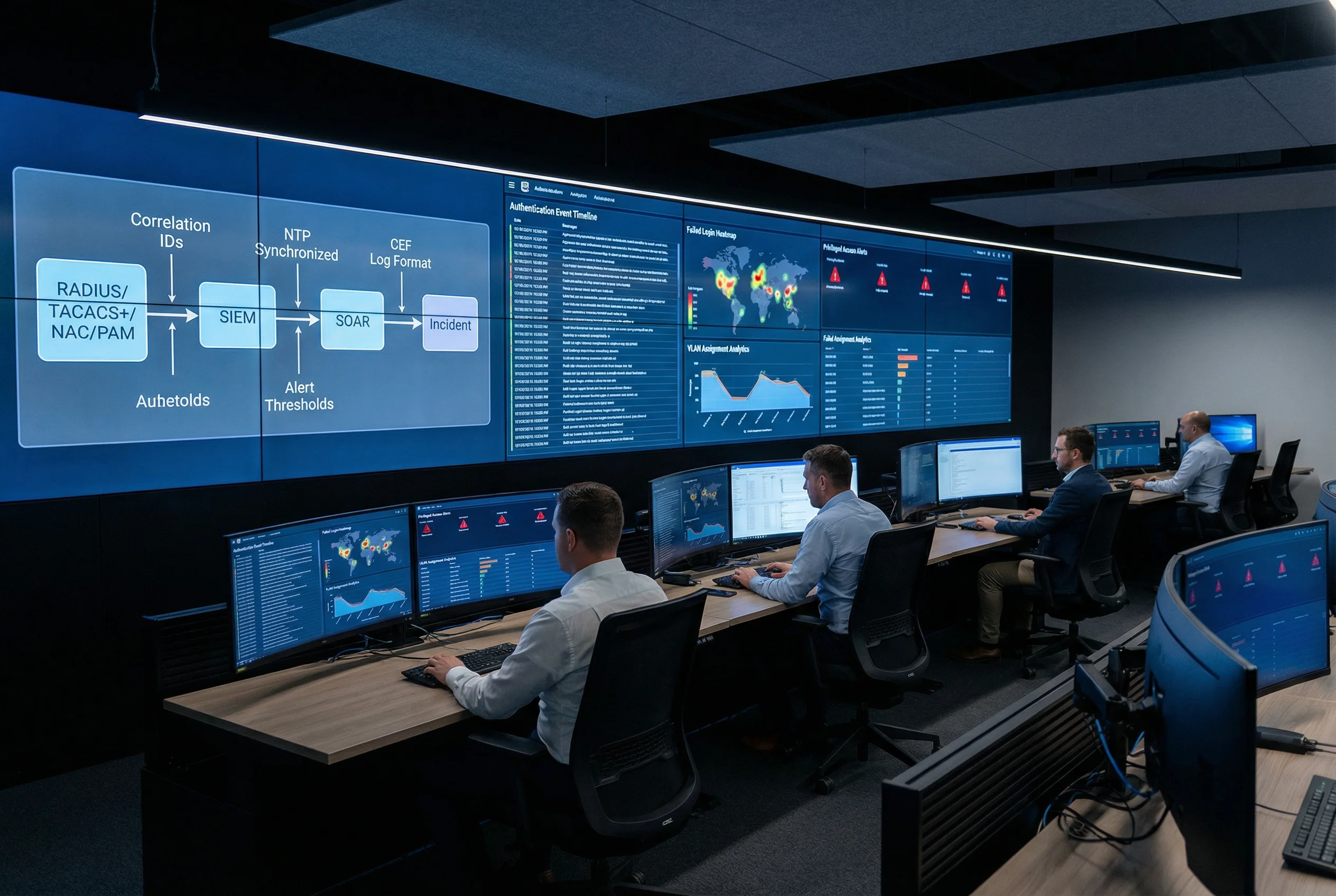
A comprehensive identity audit capability requires all authentication and authorization events to flow into a centralized SIEM with consistent log schemas, correlation IDs, and NTP-synchronized timestamps. The SIEM provides real-time dashboards for authentication event timelines, failed login heatmaps, VLAN assignment analytics, and privileged access alerts. SOAR playbooks automate incident response for high-confidence detections such as impossible travel, brute-force attacks, and unauthorized command execution. Log retention of 180–365 days supports forensic investigations and compliance reporting.
| Log Source | Key Fields | Alert Trigger | SOAR Action |
|---|---|---|---|
| RADIUS | User, device, VLAN, result, timestamp | Auth failure rate > threshold | Block MAC; notify admin |
| TACACS+ | User, device, command, result, timestamp | Unauthorized command attempt | Terminate session; open incident |
| NAC | Device, profile, VLAN, CoA, timestamp | Unknown device in sensitive zone | Quarantine; alert SOC |
| PAM | User, target, session ID, commands, recording | Break-glass usage | Notify CISO; schedule review |
| IdP | User, risk score, MFA result, app, timestamp | Impossible travel detected | Block session; force password reset |
3.1 Scenario Selection Guide
The following matrix provides a structured framework for selecting the appropriate scenario combination based on organization size, site count, device diversity, and compliance requirements. Most enterprise deployments will implement multiple scenarios simultaneously, with the combination determined by the specific risk profile and operational environment.
| Organization Profile | Primary Scenarios | Optional Scenarios | Key Drivers |
|---|---|---|---|
| Small enterprise (< 500 users, 1–3 sites) | 1 (Wired), 2 (Wi-Fi), 4 (Guest) | 5 (Remote), 8 (SIEM) | Simplicity; low OpEx; standard compliance |
| Mid-size enterprise (500–2000 users, 3–10 sites) | 1, 2, 3 (IoT), 4, 5, 6 (PAM) | 7 (Multi-site), 8 | IoT growth; remote work; audit requirements |
| Large enterprise (2000–10000 users, 10–30 sites) | All 8 scenarios | Advanced SOAR integration | Zero Trust journey; regulatory compliance; SOC maturity |
| High-security / regulated (finance, healthcare, government) | All 8 scenarios + PAM deep integration | Hardware security keys; air-gapped segments | Strict audit; SoD; privileged access controls |